Table des matières
1. Introduction
Le Transfert de Puissance Inductif (TPI) est une technologie clé pour la recharge sans fil des véhicules électriques (VE), offrant des avantages en matière de sécurité et de commodité. Une exigence critique pour la charge des batteries Lithium-ion est un profil de charge à Courant Constant (CC) indépendant de la charge, suivi d'une charge à Tension Constante (TC). Parallèlement, l'obtention d'un Angle de Phase Zéro (ZPA) à l'entrée est essentielle pour minimiser la puissance apparente nominale du convertisseur, améliorant ainsi l'efficacité et réduisant les coûts. Cet article aborde le défi de réaliser conjointement CC, TC et ZPA grâce à une nouvelle méthodologie de conception basée sur des circuits résonnants, dépassant les approches complexes basées sur des équations.
2. Concepts Fondamentaux & Revue de la Littérature
2.1. Le Défi CC-CV-ZPA dans le TPI
Le réseau de compensation dans un système TPI se situe entre l'onduleur et les bobines couplées. Sa conception détermine si la sortie se comporte comme une source de courant (CC) ou une source de tension (TC) indépendamment des variations de charge. ZPA désigne la condition où la tension et le courant d'entrée sont en phase, ce qui implique une impédance d'entrée purement résistive. Atteindre ces trois caractéristiques nécessite généralement de fonctionner à deux fréquences de résonance distinctes et de résoudre des équations de réseau complexes.
2.2. Étude des Méthodes Existantes
Les recherches antérieures ont établi des concepts fondamentaux. Les travaux clés incluent :
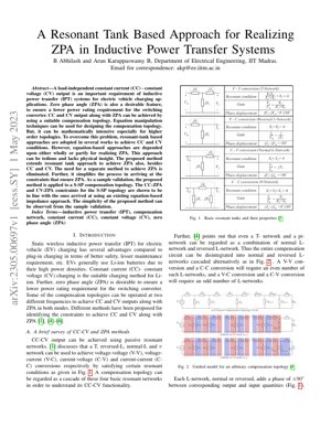
- Réseaux Résonnants de Base (T, L, π) : Identifiés comme éléments de base pour les conversions V-V, V-C, C-V et C-C [1].
- Modèle Unifié en Réseau-L : Toute topologie de compensation peut être décomposée en réseaux-L normaux et inversés en cascade, chacun contribuant à un déphasage de $± 90^\circ$ [4]. Ce modèle explique élégamment pourquoi les conversions V-V/C-C (nombre pair de réseaux-L) produisent un déphasage de $0^\circ$ ou $180^\circ$, tandis que les V-C/C-V (nombre impair) produisent $± 90^\circ$.
- Méthodes ZPA : Les approches traditionnelles impliquent de résoudre $Im(Z_{in}) = 0$ [1] ou d'utiliser des équations généralisées mais complexes [4], ce qui devient mathématiquement intensif pour les topologies d'ordre supérieur.
3. L'Approche par Circuit Résonnant Proposée
3.1. Principe Fondamental
L'innovation principale de la méthode proposée est d'étendre la philosophie de décomposition en circuits résonnants (réseaux-L) pour synthétiser directement les conditions ZPA. Au lieu de traiter le ZPA comme un problème séparé résolu par l'algèbre des impédances, la méthode intègre le ZPA comme une contrainte de conception au sein du cadre de la cascade de circuits résonnants. L'idée physique est que le ZPA peut être atteint en s'assurant que le déphasage total à travers les circuits constituants du réseau s'aligne correctement à la fréquence de fonctionnement.
3.2. Cadre Mathématique & Contraintes
L'analyse exploite les propriétés de phase des réseaux-L. Pour une topologie représentée comme une cascade de $n$ réseaux-L, le déphasage total entre les grandeurs d'entrée et de sortie est $n \times (± 90^\circ)$. Pour un ZPA à l'entrée, l'impédance d'entrée du réseau doit être réelle. Cela impose des conditions sur les impédances des circuits individuels. Pour une topologie à sortie CC (se comportant comme une source de courant), la méthode proposée dérive des contraintes en analysant simultanément la fonction de transfert du réseau de circuits et son impédance d'entrée d'un point de vue circuit. Les équations clés impliquent de fixer à zéro la partie imaginaire de l'admittance (ou impédance) d'entrée dérivée du modèle de circuit : $Im(Y_{in, circuit}) = 0$. Cela se simplifie souvent en conditions de résonance sur des composants spécifiques du circuit.
4. Validation & Résultats
4.1. Application à la Topologie S-SP
L'article valide la méthode en utilisant une topologie de compensation Série-Série-Parallèle (S-SP), un réseau d'ordre supérieur courant. Le circuit S-SP est décomposé en ses circuits résonants constitutifs (par exemple, un circuit série suivi d'un réseau-L).
4.2. Résultats Expérimentaux/Simulation
Il est démontré que les contraintes CC-ZPA et TC-ZPA dérivées pour la topologie S-SP en utilisant la méthode basée sur les circuits sont identiques à celles obtenues par la méthode plus laborieuse basée sur les équations d'impédance [4,5]. Cela sert de preuve de correction. Le résultat principal est démonstratif : Simplicité. Le processus de dérivation est nettement plus intuitif et nécessite moins de manipulations algébriques. Des graphiques ou des formes d'onde de simulation montreraient typiquement : 1) Le courant de sortie ($I_o$) restant constant face à une variation de la résistance de charge ($R_L$) à la fréquence CC, avec la tension et le courant d'entrée en phase. 2) La tension de sortie ($V_o$) restant constante face à une variation de $R_L$ à la fréquence TC, à nouveau avec ZPA. La courbe d'efficacité montrerait probablement des pics à ces fréquences ZPA conçues.
Idée Maîtresse de Conception
Le ZPA n'est pas un puzzle indépendant ; c'est une propriété géométrique de la cascade de circuits résonnants. Concevoir pour CC/TC avec la bonne séquence de circuits définit intrinsèquement le chemin vers le ZPA.
5. Analyse Technique & Cadre
5.1. Idée Maîtresse & Enchaînement Logique
Idée Maîtresse : La percée fondamentale de l'article est un changement de paradigme, passant d'un calcul analytique à une synthèse topologique pour le ZPA. La plupart des travaux antérieurs, y compris des travaux influents d'institutions comme le MIT et UC Berkeley sur la modélisation des convertisseurs résonnants, traitent le réseau de compensation comme une boîte noire dont l'impédance doit être résolue. Cet article soutient que la boîte est transparente et constituée de blocs Lego connus (circuits-L). L'enchaînement logique est impeccable : (1) Tous les réseaux de compensation sont des cascades de circuits-L. (2) Chaque circuit impose un déphasage fixe de $90^\circ$. (3) Par conséquent, la réponse en phase du réseau est prédéterminée par sa séquence de circuits. (4) Ainsi, le ZPA devient une question de choix des valeurs des composants au sein de cette structure à phase fixe pour annuler toute réactance résiduelle. C'est analogue à la philosophie derrière CycleGAN qui utilise une structure fixe générateur-discriminateur pour apprendre le transfert de style sans données appariées—l'architecture impose l'espace de solution.
5.2. Forces & Faiblesses Critiques
Forces :
- Élégance & Valeur Pédagogique : Elle fournit une intuition physique profonde. Les ingénieurs peuvent désormais "voir" le ZPA dans le schéma de circuit.
- Accélération de la Conception : Réduit considérablement le temps et la barrière de compétence pour dériver des contraintes pour de nouvelles topologies.
- Unification : Unifie élégamment la conception CC, TC et ZPA en un seul cadre cohérent basé sur les circuits.
- Validation Pratique Limitée : La prépublication arXiv (v1) montre principalement une équivalence mathématique avec les anciennes méthodes, pas des résultats matériels. Où sont les courbes d'efficacité, les données de performance thermique et l'analyse de sensibilité aux tolérances des composants ? Une méthode revendiquant la simplicité doit prouver sa robustesse dans le monde réel imparfait.
- Silence sur les Non-idéalités : Elle suppose des bobines et condensateurs idéaux. L'analyse s'effondre probablement en cas de désalignement significatif des bobines ou de variation de couplage ($k$), qui est le fléau de tous les systèmes TPI. Les références du programme de recharge sans fil du Oak Ridge National Laboratory soulignent constamment la tolérance au couplage comme un défi de recherche majeur.
- Question d'Évolutivité : Bien que plus simple pour la dérivation, conduit-elle à des valeurs de composants plus simples ou à des tolérances plus strictes ? L'article ne compare pas la réalisabilité pratique des valeurs de composants dérivées via cette méthode par rapport à d'autres.
5.3. Perspectives Actionnables & Implications
Pour les Responsables R&D et les Architectes en Électronique de Puissance :
- Adopter comme Outil de Formation aux Premiers Principes : Intégrez ce cadre basé sur les circuits dans l'intégration de votre équipe pour la conception TPI. Cela créera une compréhension fondamentale plus solide que de distribuer des feuilles d'équations dérivées.
- Utiliser pour un Criblage Rapide des Topologies : Lors de l'évaluation d'une nouvelle topologie à 4 bobines ou hybride, utilisez cette méthode pour cartographier rapidement ses capacités théoriques CC-TC-ZPA avant de vous engager dans une simulation détaillée. C'est un filtre rapide.
- Exiger une Validation Étendue : Avant de mettre en œuvre cette méthode dans un produit, commandez des études pour tester sa robustesse face aux variations de couplage et aux tolérances des composants. L'idée centrale est prometteuse, mais sa valeur technique n'est pas prouvée.
- Combler l'Écart avec l'Optimisation : La prochaine étape logique est de combiner ce cadre intuitif avec une optimisation des composants basée sur l'IA/ML (par exemple, en utilisant des algorithmes similaires à ceux de la recherche d'architecture neuronale) pour trouver des topologies à la fois fonctionnellement élégantes (ZPA) et pratiquement optimales (efficacité, coût, taille).
6. Applications Futures & Orientations
L'approche par circuit résonnant ouvre plusieurs voies futures :
- Synthèse de Topologie Assistée par IA : En utilisant le réseau-L comme élément de base fondamental, des algorithmes génératifs pourraient proposer et évaluer automatiquement de nouvelles topologies de compensation garantissant le ZPA pour des spécifications données.
- Systèmes TPI Dynamiques : Pour la recharge dynamique des VE (en mouvement) où le couplage varie rapidement, ce cadre pourrait être utilisé pour concevoir des réseaux de compensation adaptatifs où les paramètres des circuits sont commutés ou ajustés sélectivement pour maintenir le ZPA.
- Intégration avec les Semi-conducteurs à Large Bande Interdite : Combiner cette méthode de conception avec des onduleurs haute fréquence basés sur GaN/SiC peut conduire à des chargeurs sans fil ultra-compacts et à haute efficacité. Le fonctionnement ZPA minimise les pertes par commutation et la contrainte sur ces dispositifs.
- Au-delà des VE : Application dans les implants biomédicaux (où l'efficacité et la sécurité sont primordiales), l'électronique grand public et les systèmes de puissance sans fil industriels où une sortie indépendante de la charge est souhaitable.
7. Références
- Auteurs, "Titre sur les réseaux résonnants de base," Journal/Conférence, 201X.
- J.-Y. Zhu, T. Park, P. Isola, et al., "Unpaired Image-to-Image Translation using Cycle-Consistent Adversarial Networks," IEEE ICCV, 2017. (Cité comme une analogie pour la résolution de problèmes structurés).
- Oak Ridge National Laboratory, "Wireless Power Transfer for Electric Vehicles," [En ligne]. Disponible : https://www.ornl.gov/ (Cité pour les défis techniques du monde réel).
- Auteurs, "Titre sur le modèle unifié en réseau-L," Journal, 201Y.
- Auteurs, "Titre sur la condition ZPA du réseau-T," Journal, 201Z.
- B. Abhilash et A. K. B, "A Resonant Tank Based Approach for Realizing ZPA in Inductive Power Transfer Systems," arXiv:2305.00697, 2023.