Table of Contents
1. Introduction
Inductive Power Transfer (IPT) is a cornerstone technology for wireless Electric Vehicle (EV) charging, offering advantages in safety and convenience. A critical requirement for charging Lithium-ion batteries is a load-independent Constant Current (CC) followed by a Constant Voltage (CV) charging profile. Simultaneously, achieving Zero Phase Angle (ZPA) at the input is essential to minimize the volt-ampere rating of the power converter, improving efficiency and reducing cost. This paper addresses the challenge of jointly achieving CC, CV, and ZPA through a novel resonant tank-based design methodology, moving beyond complex equation-based approaches.
2. Core Concepts & Literature Review
2.1. The CC-CV-ZPA Challenge in IPT
The compensation network in an IPT system sits between the inverter and the coupled coils. Its design dictates whether the output behaves as a current source (CC) or a voltage source (CV) independent of load variations. ZPA refers to the condition where the input voltage and current are in phase, implying a purely resistive input impedance. Achieving all three features typically requires operating at two distinct resonant frequencies and solving complex network equations.
2.2. Survey of Existing Methods
Prior research has established foundational concepts. Key works include:
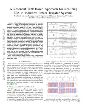
- Basic Resonant Networks (T, L, π): Identified as building blocks for V-V, V-C, C-V, and C-C conversions [1].
- Unified L-Network Model: Any compensation topology can be decomposed into cascaded normal and reversed L-networks, each contributing a $\pm 90^\circ$ phase shift [4]. This model elegantly explains why V-V/C-C conversions (even number of L-networks) yield $0^\circ$ or $180^\circ$ phase shift, while V-C/C-V (odd number) yield $\pm 90^\circ$.
- ZPA Methods: Traditional approaches involve solving $Im(Z_{in}) = 0$ [1] or using generalized but complex equations [4], which become mathematically intensive for higher-order topologies.
3. The Proposed Resonant Tank Approach
3.1. Fundamental Principle
The proposed method's core innovation is extending the resonant tank (L-network) decomposition philosophy to directly synthesize ZPA conditions. Instead of treating ZPA as a separate problem solved via impedance algebra, the method integrates ZPA as a design constraint within the resonant tank cascade framework. The physical insight is that ZPA can be achieved by ensuring the total phase shift through the network's constituent tanks aligns correctly at the operating frequency.
3.2. Mathematical Framework & Constraints
The analysis leverages the phase properties of L-networks. For a topology represented as a cascade of $n$ L-networks, the total phase shift between input and output quantities is $n \times (\pm 90^\circ)$. For ZPA at the input, the network's input impedance must be real. This imposes conditions on the impedances of the individual tanks. For a CC-output topology (e.g., behaving as a current source), the proposed method derives constraints by analyzing the tank network's transfer function and its input impedance simultaneously from a tank perspective. The key equations involve setting the imaginary part of the input admittance (or impedance) derived from the tank model to zero: $Im(Y_{in, tank}) = 0$. This often simplifies to resonant conditions on specific tank components.
4. Validation & Results
4.1. Application to S-SP Topology
The paper validates the method using a Series-Series-Parallel (S-SP) compensation topology, a common higher-order network. The S-SP circuit is decomposed into its constituent resonant tanks (e.g., a series tank followed by an L-network).
4.2. Experimental/Simulation Outcomes
The derived CC-ZPA and CV-ZPA constraints for the S-SP topology using the proposed tank-based method are shown to be identical to those obtained from the more laborious equation-based impedance method [4,5]. This serves as proof of correctness. The primary result is demonstrative: Simplicity. The derivation process is significantly more intuitive and requires less algebraic manipulation. Charts or simulation waveforms would typically show: 1) Output current ($I_o$) remaining constant against varying load resistance ($R_L$) at the CC frequency, with input voltage and current in phase. 2) Output voltage ($V_o$) remaining constant against varying $R_L$ at the CV frequency, again with ZPA. The efficiency plot would likely show peaks at these designed ZPA frequencies.
Key Design Insight
ZPA is not an independent puzzle; it's a geometric property of the resonant tank cascade. Designing for CC/CV with the right tank sequence inherently defines the path to ZPA.
5. Technical Analysis & Framework
5.1. Core Insight & Logical Flow
Core Insight: The paper's fundamental breakthrough is a paradigm shift from analytical computation to topological synthesis for ZPA. Most prior art, including influential works from institutions like MIT and UC Berkeley on resonant converter modeling, treats the compensation network as a black box whose impedance needs to be solved. This paper argues that the box is transparent and made of known Lego blocks (L-tanks). The logical flow is impeccable: (1) All compensation networks are L-tank cascades. (2) Each tank imposes a fixed $90^\circ$ phase shift. (3) Therefore, the network's phase response is predetermined by its tank sequence. (4) Ergo, ZPA becomes a matter of choosing component values within this fixed-phase structure to cancel any residual reactance. It's akin to the philosophy behind CycleGAN's use of a fixed generator-discriminator structure to learn style transfer without paired data—the architecture enforces the solution space.
5.2. Strengths & Critical Flaws
Strengths:
- Elegance & Pedagogical Value: It provides profound physical intuition. Engineers can now "see" ZPA in the circuit diagram.
- Design Acceleration: Dramatically reduces the time and skill barrier for deriving constraints for novel topologies.
- Unification: Elegantly unifies CC, CV, and ZPA design into a single, coherent tank-based framework.
- Limited Practical Validation: The arXiv preprint (v1) primarily shows mathematical equivalence to old methods, not hardware results. Where are the efficiency curves, thermal performance data, and sensitivity analysis to component tolerances? A method claiming simplicity must prove it's robust in the messy real world.
- Silence on Non-Idealities: It assumes ideal coils and capacitors. The analysis likely breaks down under significant coil misalignment or coupling variation ($k$), which is the bane of all IPT systems. References from Oak Ridge National Laboratory's wireless charging program consistently highlight coupling tolerance as a top research challenge.
- Scalability Question: While simpler for derivation, does it lead to simpler component values or more stringent tolerances? The paper doesn't compare the practical realizability of component values derived via this method versus others.
5.3. Actionable Insights & Implications
For R&D Managers and Power Electronics Architects:
- Adopt as a First-Principles Training Tool: Integrate this tank-based framework into your team's onboarding for IPT design. It will create a stronger foundational understanding than handing out derived equation sheets.
- Use for Rapid Topology Screening: When evaluating a new 4-coil or hybrid topology, use this method to quickly map out its theoretical CC-CV-ZPA capability before committing to detailed simulation. It's a fast filter.
- Demand Extended Validation: Before implementing this in a product, commission studies to test its robustness against coupling variation and component tolerances. The core idea is promising, but its engineering worth is unproven.
- Bridge the Gap with Optimization: The next logical step is to combine this intuitive framework with AI/ML-based component optimization (e.g., using algorithms similar to those in neural architecture search) to find topologies that are both functionally elegant (ZPA) and practically optimal (efficiency, cost, size).
6. Future Applications & Directions
The resonant tank approach opens several future avenues:
- AI-Assisted Topology Synthesis: Using the L-network as a fundamental building block, generative algorithms could automatically propose and evaluate new compensation topologies that guarantee ZPA for given specifications.
- Dynamic IPT Systems: For dynamic (in-motion) EV charging where coupling varies rapidly, this framework could be used to design adaptive compensation networks where tank parameters are selectively switched or tuned to maintain ZPA.
- Integration with Wide-Bandgap Semiconductors: Combining this design method with GaN/SiC-based high-frequency inverters can lead to ultra-compact, high-efficiency wireless chargers. The ZPA operation minimizes switching losses and stress on these devices.
- Beyond EVs: Application in biomedical implants (where efficiency and safety are paramount), consumer electronics, and industrial wireless power systems where load-independent output is desirable.
7. References
- Authors, "Title on basic resonant networks," Journal/Conference, 201X.
- J.-Y. Zhu, T. Park, P. Isola, et al., "Unpaired Image-to-Image Translation using Cycle-Consistent Adversarial Networks," IEEE ICCV, 2017. (Cited as an analogy for structured problem-solving).
- Oak Ridge National Laboratory, "Wireless Power Transfer for Electric Vehicles," [Online]. Available: https://www.ornl.gov/ (Cited for real-world engineering challenges).
- Authors, "Title on unified L-network model," Journal, 201Y.
- Authors, "Title on T-network ZPA condition," Journal, 201Z.
- B. Abhilash and A. K. B, "A Resonant Tank Based Approach for Realizing ZPA in Inductive Power Transfer Systems," arXiv:2305.00697, 2023.